How to make a simple line following robot using Arduino uno
Line following robot
In this tutorial I am gonna show you how to make a simple line following robot using IR sensors and ARDUINO UNO.I will be providing very easy and effective code that will help you to solve maze containing 90°,45° angles and curves.So les get started.
Components required:
1.Arduino uno board
2.L293D motor driver IC
3.IR sensors(here i am using 5 sensors for the perfection of the robot)
4.Chassis
5.BO motors(two)
6.Castro wheel(one)
7.Batteries
8.Power bank(to power the ARDUINO)
Steps to be followed:
Step-1
Assemble BO motors and Castro wheel on the chassis as shown in the figure.
 |
| Note: This is an example,my real robot have hand made chassis but the process is same. |
Step-2
Now place the battery and the Arduino uno board on the top of the chassis as shown.Connect the two batteries in series to get 8V out put.
Step-3
Connect the motors and power source to the L293D IC as shown in the figure
 |
| The polarity of the motors can be changed by altering the pin no. jack if the motor does not spin in the right direction |
We will write the programme for the pin number of the signal pin connecting the Arduino uno board.
Step-5
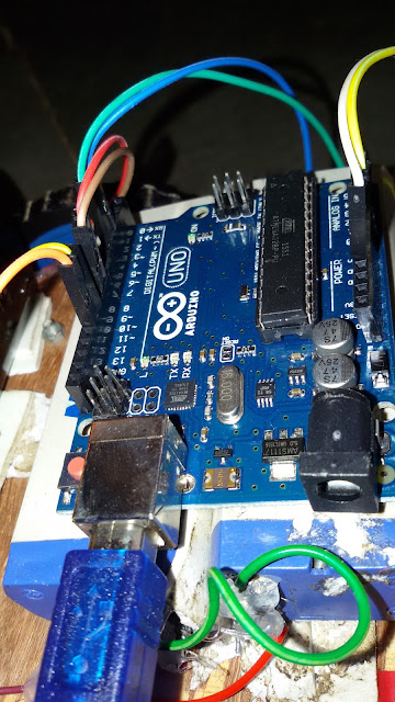
Connect the power bank,motor driver IC and sensor with the Arduino board.
Step-6
Place the 5 IR sensor as shown in the photo.We will consider sensor 1,2,3,4 and 5 form the left side of the robot keeping the robot's BACK towards us.
S5 S4 S3 S2 S1
Step-7
Now connect the

Step-8
Its coding time.Open your arduino compiler and connect the usb cable to your pc of your arduino. Copy and paste the following code and upload it to the board.
connect the RIGHT MOTOR pin to pin number 6 and 9 of the arduino. Connect the LEFT MOTOR pin to the arduino pin number 10 and 11. Connect the sensors to the pin number 1,2,3,4 and 5 to the digital pin of the arduino board taking the sensor 1 to sensor 5 from the left side of the robot.
int motorpin1 =6;
int motorpin2 = 9;
int moterpin3 = 10;
int motorpin4 = 11;
int sensor1 = 1;
int sensor2 = 2;
int sensor3 = 3;
int sensor4 = 4;
int sensor5 = 5;
void setup()
{
pinMode (1, INPUT);
pinMode (6, OUTPUT);
pinMode (9, OUTPUT);
pinMode (2, INPUT);
pinMode (10, OUTPUT);
pinMode (11, OUTPUT);
pinMode (3,INPUT);
pinMode (4,INPUT);
pinMode (5,INPUT);
}
void loop()
{
sensor1= digitalRead(1);
sensor2= digitalRead(2);
sensor3= digitalRead(3);
sensor4= digitalRead(4);
sensor5= digitalRead(5);
if(sensor1 == HIGH && sensor2 == HIGH && sensor3 == LOW && sensor4 == HIGH && sensor5 == HIGH)
{
digitalWrite(10,HIGH);
digitalWrite(11,LOW);
digitalWrite(6,HIGH);
digitalWrite(9,LOW);
}
else if(sensor1 == HIGH && sensor2 == HIGH && sensor3 == LOW && sensor4 == LOW && sensor5 == LOW)
{
digitalWrite(10,HIGH);
digitalWrite(11,LOW);
digitalWrite(6,LOW);
digitalWrite(9,LOW);
}
else if(sensor1 == LOW && sensor2 == LOW && sensor3 == LOW && sensor4 == HIGH && sensor5 == HIGH)
{
digitalWrite(10,LOW);
digitalWrite(11,LOW);
digitalWrite(6,HIGH);
digitalWrite(9,LOW);
}
else
{
digitalWrite(10,LOW);
digitalWrite(11,LOW);
digitalWrite(6,LOW);
digitalWrite(9,LOW);
}
}
Step-9


Superb bro...
ReplyDeleteThnks for making us aware about awsm robotics projects...
Welcome bro
Deletehi, thanks for the project. where can get the parts ?
ReplyDeleteyou can order from several online shopping site like ROBOMART.COM or HOBBYKING.COM..These type of parts are also available in many hobby shop or robotics shop...thank you
Deletesir i prepare line following robot using five sinsors using H-bridge L298.and i upload the given code to aurdino but its not working correctly.plz help me i am trying from one week but its not working.
ReplyDeletecheck the proper connection from arduino to motor driver and motor driver to wheels.
DeleteUse the code given above...